

Best Vision Measuring Machine for Precision Quality Control
2026-10-16
Precision quality control has a dirty secret: most measurement errors aren’t caused by bad parts—they’re caused by the instruments we trust to inspect them. If your current vision measuring machine hesitates on edges, drifts with temperature, or buries critical data in clunky software, you’re not measuring parts anymore; you’re measuring uncertainty. That’s why choosing the best vision measuring machine for precision quality control is less about megapixels and more about metrology integrity. At JATEN, we build systems that treat every micron as a fact, not a guess. In this post, we’ll show you what to look for—and what to avoid—so your quality lab stops being the bottleneck and starts being the proof.
How Vision Measuring Machines Handle Complex Geometric Tolerances
Vision measuring machines approach complex geometric tolerances by replacing tactile point sampling with a full field of view. A high resolution camera paired with telecentric optics captures the entire feature outline in one shot, so the system can evaluate position, profile, and runout without the probe deflection or datum setup errors that often affect contact methods. The software then extracts measured edges and fits them to nominal geometry, using the same datum reference frames called out on the drawing. That means a bore pattern with a tight true position tolerance gets checked as a set of coordinate deviations from a best fit center, rather than as an isolated bore-to-bore distance.
For tolerances tied to material condition modifiers, the machines read the actual local sizes first and then apply the bonus tolerance dynamically. If a pin is produced near its least material condition, the position tolerance window shrinks accordingly, and the vision system flags the exact location where the surface envelope breaks. Complex freeform profiles are handled by stitching multiple exposures or using structured light sensors, after which the point cloud is aligned to the CAD model using a best fit routine. The resulting deviation map shows where the surface sits inside or outside the tolerance band, often down to a few microns.
One practical advantage is repeatability across production runs. Once the measurement routine is built, the same lighting, focus, and edge detection parameters fire every cycle without operator influence, so true position, symmetry, and surface profile results stay comparable from first article to final inspection. When a part drifts out of spec, the data also shows whether the problem is a shifted datum, a form error, or a size issue, which helps narrow down the machining process instead of just rejecting parts.
Software Choices That Make or Break Measurement Repeatability
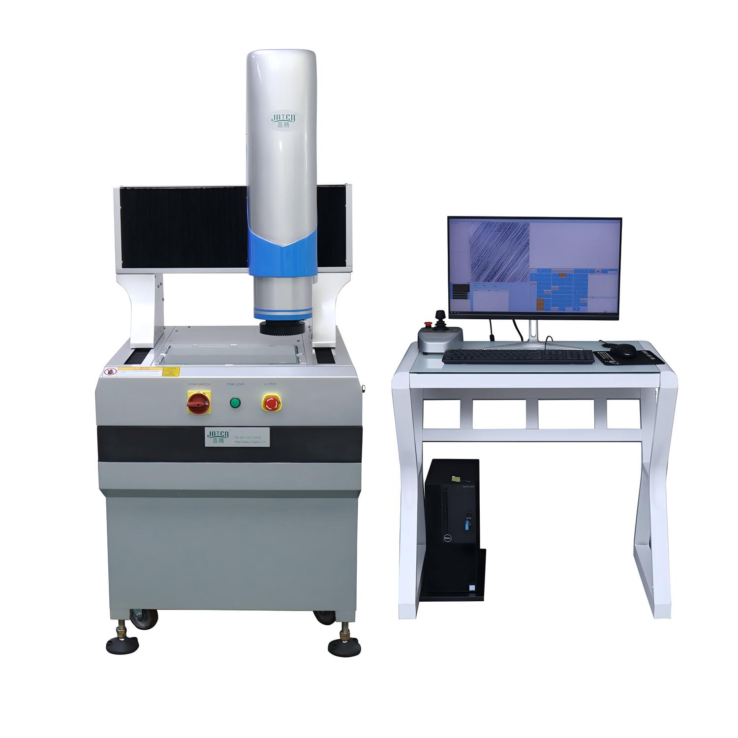
Measurement repeatability isn't just about the instrument; the software that processes raw readings often decides whether you get the same number twice. Some platforms quietly apply baseline corrections or smoothing steps without showing the settings, so two operators using the same file can produce different results without realizing why. A reliable setup logs every processing parameter and software version, making it possible to re-run an old measurement and match the original output exactly.
Another breaker is too much manual control. When an interface invites users to drag regions, pick peaks, or exclude outliers on screen, each person leaves a fingerprint on the data. Repeatability improves when the software locks down the workflow—raw import, calibration, normalization, and reporting happen in a fixed order with no ad-hoc adjustments. The least exciting software often delivers the most consistent measurements because it removes the temptation to 'help' the result.
Version discipline and file formats also matter. A vendor update that silently changes an algorithm can make last month's data impossible to reproduce. Keeping an installation snapshot or exporting to open, documented formats preserves repeatability across machines and years. In practical terms, choosing software is not just a usability decision; it is a direct vote for or against measurement repeatability.
Selecting the Right Optical System for High-Mix Production
High-mix manufacturing environments rarely reward a single, fixed optical configuration. The part geometries, surface finishes, and feature sizes can shift from one job to the next, often within the same shift. A telecentric lens that works beautifully for measuring small connector pins may introduce unacceptable distortion or field-of-view limitations when the line switches to a larger stamped bracket. Rather than chasing a universal solution, production engineers should evaluate the optical front end as a modular subsystem—interchangeable lenses, adjustable working distances, and lighting that can be reconfigured without forcing a complete system redesign.
Resolution and depth of field demand careful trade-offs when part variety is high. A system optimized for fine surface defects on polished metal will struggle with a matte plastic component unless the aperture, magnification, and illumination are retuned. Keeping a small set of validated optical recipes—stored per part number or family—lets operators swap configurations in minutes instead of hours. The key is to standardize the mounting interfaces and calibration targets so that any change in lens or camera position is repeatable, not a fresh alignment project each time.
Finally, consider the long-term cost of optical complexity. High-mix lines often drift toward over-engineered setups that try to cover every possible part with excessive resolution or oversized sensors. This inflates both hardware expense and processing load. A better approach is to define the minimum optical performance needed for the most demanding part in the current mix, then build in a modest margin. That leaves room for unexpected new products without locking the line into a fragile, overly specialized configuration that becomes a bottleneck when the mix evolves again.
What Happens When Calibration Drift Goes Unnoticed
Over time, even the most reliable instruments shift away from their reference standards—often by fractions that seem negligible on any single reading. The trouble is that these tiny deviations compound silently across production runs, lab tests, or field measurements. A torque wrench that reads just 2% low may still tighten bolts within spec on Monday, but by Thursday every fastener on the line is slightly under-torqued. Because the drift is gradual, operators stop noticing the change; the “new normal” masks the error until a downstream failure forces an investigation.
When calibration drift slips past routine checks, the consequences rarely announce themselves immediately. In a quality control lab, an uncalibrated spectrophotometer can pass batches of material that are actually out of tolerance, meaning defective product reaches customers before anyone sees a red flag. In medical settings, a blood gas analyzer that has drifted high by a few percent can alter treatment decisions—pushing a borderline patient toward unnecessary intervention or masking a critical decline. The common thread is that the error becomes embedded in the decision-making process, making it harder to trace back to its source once the damage is done.
What makes unnoticed drift especially dangerous is that it erodes trust in the entire measurement system. Staff begin compensating empirically—nudging values, rechecking suspicious results, or discarding outliers that don’t fit expected patterns—without realizing they are adjusting for a systematic bias. Over weeks or months, the official records look stable even as the underlying process drifts further from truth. By the time a major discrepancy surfaces, the audit trail is muddled, the root cause is buried under layers of workaround, and the cost of correction far exceeds what a scheduled calibration would have been.
Why Reflective Surfaces Challenge Even the Best Vision Systems
Most cameras assume light bounces off objects in a predictable, diffuse way. A matte wall scatters light evenly, so the sensor sees a stable patch of color. A reflective surface breaks that assumption. Instead of scattering, it throws light back in concentrated directions, creating bright spots that shift as the viewing angle changes. A robot trying to gauge distance or identify a surface suddenly faces data that looks nothing like the physical object.
The problem gets worse when reflections turn into ghost images. A polished metal part can show a perfect mirror image of the room around it, including lights, people, or other machinery. Standard vision pipelines often treat those mirrored details as real geometry. The result is false edges, phantom objects, and depth maps that suggest surfaces floating in mid-air. Even high-resolution cameras with excellent dynamic range can be fooled, because the issue isn't resolution but the fact that the sensor records light, not meaning.
Some systems try to compensate with multiple exposures or polarized filters, but those add cost and complexity. More fundamentally, reflective surfaces force a question: is the vision system seeing the object or seeing the environment? Until that ambiguity is resolved, even the most advanced neural networks will hesitate at a chrome bumper or a glass door.
Moving Toward Paperless Quality Control with Vision Metrology
The drift away from printed inspection reports starts with the measurement itself. Vision metrology systems capture surface coordinates, edge profiles, and feature locations directly into software, so the first recording is already digital. There is no transcribing from a handheld gauge to a sheet of paper, which removes a major source of manual error.
Once the data lives in a structured file, it can move through review cycles without waiting for a paper form to circulate. Engineers pull up the same measurement session on a tablet or workstation, add notes next to the relevant point cloud or image frame, and approve or reject the result in place. This keeps the quality record tied to the actual geometry, not to a scanned copy of a signature.
The final benefit shows up during traceability requests or audits. Digital metrology logs retain the full context: the sensor used, the alignment routine, the date and time, and the operator's sign-off. Retrieving a past job becomes a search task instead of a file-hunting task, and the record cannot be misplaced or altered by coffee spills.
FAQ
It rarely comes down to a single spec. The frame has to resist thermal drift, the stage needs repeatable motion, and the edge-detection algorithm must handle low-contrast edges without guessing. In practice, you want a system that holds sub-micron repeatability on your own parts, not just on a calibration artifact.
Lighting usually wins. More megapixels can expose more pixels, but if the edge is washed out or buried in shadow, the extra resolution just gives you a sharper picture of a bad measurement. A machine with switchable coaxial, ring, and transmitted light will handle far more real-world surfaces.
Look at how fast a new part program can be created. If the software lets you import CAD, click on features, and auto-generate a measurement routine, then switching from one part number to the next stays practical. Machines that demand long script-writing sessions for every new job become bottlenecks, no matter how fast the stage moves.
Pass/fail is only the beginning. The software should give you clear graphical reports, allow tolerance band comparisons, and export data to SPC or quality management systems without manual copying. That way trends become visible before parts drift out of spec, and the machine becomes a process control tool rather than a fancy go/no-go gauge.
Keep the glass scale and stage clean, avoid touching optical surfaces with bare hands, and run a quick verification artifact check at the start of each shift. Temperature swings in the room will cause more drift than most people expect, so a stable environment matters as much as annual calibration.
If your parts include deep bores, highly reflective surfaces, or features that are hard to light from above, adding a touch probe or laser can fill those gaps. Vision-only systems struggle with edges that are physically hidden. A multisensor setup costs more up front, but it prevents you from needing a second machine later.
Beyond the purchase price, consider the granite base or vibration isolation if your floor isn't solid, compressed air if air bearings are used, and the time for operator training. Also check whether the software license covers all measurement functions or if advanced modules like CAD comparison or SPC reporting are locked behind extra fees.
Conclusion
Selecting the best vision measuring machine for precision quality control demands more than raw accuracy specs. In practice, the system must handle complex geometric tolerances across varied parts without constant reprogramming. The optical configuration matters heavily in high-mix production: a fixed telecentric lens may excel on flat stampings but struggle with reflective or multi-level surfaces, so interchangeable lighting and sensor options often prove decisive. Software is the quieter differentiator. Measurement repeatability hinges on edge-detection algorithms, automated focus routines, and how well the package manages coordinate systems from batch to batch. A machine that drifts a few microns between calibrations can pass internal checks while shipping defective dimensions. Reflective surfaces compound this risk because specular highlights shift with tiny angular changes, fooling weaker edge tools and producing false passes.
The strongest choices pair robust optics with software that exposes uncertainty rather than hiding it. Calibration drift needs to be visible through routine verification artifacts, not buried in annual service reports. In facilities pushing toward paperless quality control, the vision system should feed dimensional data directly into SPC and traceability workflows without manual transcription. When these elements align—stable measurements on shiny or textured parts, quick changeovers in high-mix environments, and trustworthy digital records—the result is a quality platform that reduces inspection bottlenecks. Ultimately, the best vision measuring machine is the one that stays dependable under real production lighting and operator turnover, not just in a controlled demo room.
Contact Us
Contact Person: Volien
Email: [email protected]
Tel/WhatsApp: +86 18029161762
Website: https://www.jatentech.com/