

Custom Type B RCD: What to Consider for Tailored Electrical Safety
2026-10-12
Think a standard Type B RCD will cover your installation? That assumption can quietly backfire when harmonics, DC leakage, or unusual load profiles enter the picture. Custom Type B RCDs are not just about swapping ratings—they demand a closer look at trip thresholds, frequency response, and environmental stress. At ETEK, we’ve learned that the most reliable protection starts with sharper questions, not a bigger spec sheet. Before you lock in a design, here’s what actually deserves your attention.
The DC Leakage Standard Protection Overlooks
Most leakage current standards fixate on steady-state AC leakage, but they rarely account for the irregular, transient DC leakage that modern switching power supplies and renewable energy inverters can produce. The assumption that leakage is purely sinusoidal or slowly varying breaks down when high-frequency switching noise couples through parasitic capacitances into grounding conductors. This oversight means a circuit can pass certification while still emitting dangerous DC currents under certain load conditions.
Another blind spot is the protection threshold itself. Standards often specify a maximum allowable DC leakage in ideal conditions, such as a fixed temperature and clean mains voltage. Real installations, however, experience degraded insulation, humidity, and aging components that push actual leakage far above the lab-measured value. Because protection devices are designed to trip at the standard’s threshold, they may fail to respond to a slow drift into a hazardous DC fault that never crosses the clean-sinusoid test profile.
Finally, the interaction between AC and DC leakage is seldom addressed. When a DC bias saturates a residual current device’s core, its ability to detect AC leakage drops dramatically. Some standards mention this vaguely but do not mandate testing with mixed AC/DC waveforms. As a result, a system can appear compliant on paper while its protective relay is effectively deaf to the very faults it was designed to catch.
Reading Inverter and Drive Loads Before You Specify
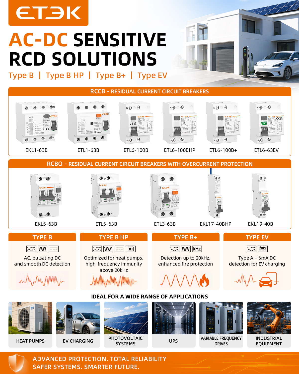
Sizing an inverter or drive without first reading the actual load profile is like prescribing medicine without checking the patient's symptoms. You might get lucky, but more often you'll end up with nuisance trips, premature component failure, or wasted capacity. The load isn't just a number on a nameplate; it's a dynamic set of demands that shift with speed, torque, and duty cycle. Before you circle a part number, map out what the driven equipment really asks for at startup, steady state, and peak operation. That means looking beyond horsepower or kilowatts to the torque curve, reflected inertia, and any regenerative braking requirements.
A common oversight is assuming that a constant-torque load behaves like a variable-torque one, or forgetting that a conveyor's breakaway torque can be double its running torque. Drives are rated for specific overload conditions—typically 150% for one minute or 200% for a few seconds—and exceeding those margins even briefly can trigger faults or shorten component life. Also consider the environment: high ambient temperatures or poor ventilation derate a drive's continuous current capacity. By reading the full load profile, including any cyclic or shock loads, you can choose a drive that operates comfortably within its thermal and electrical limits rather than one that limps along at the edge of its rating.
Another layer to examine is harmonic distortion and power factor, especially on larger systems. Non-linear loads from drives can interact with other equipment on the same bus, so checking the total harmonic demand before specifying helps avoid needing expensive filters later. Ask how often the load starts and stops per hour, whether it ever reverses direction, and what happens during a power sag—those details shape the drive's braking resistor size, DC bus capacitance, and control strategy. Good load reading isn't just about preventing failure; it's about matching the drive to the machine's real behavior so you don't pay for unused headroom or, worse, undersize and eat the cost of downtime.
Setting Trip Sensitivity Around Real Leakage, Not Guesswork
Leakage current varies with cable length, insulation age, humidity, and the number of connected loads. Guessing a trip threshold often leaves it either too high to catch real faults or too low to avoid nuisance trips. A better starting point is to measure baseline leakage with a clamp meter while the circuit runs under normal load, then set the trip point just above that observed value—not at some generic fraction pulled from a table.
Once the baseline is known, account for the loads that cycle on and off. Motors, heaters, and drives can add short bursts of leakage that settle after startup. Record those peaks before adjusting sensitivity, because a setting that ignores them will trip randomly and erode trust in the protection. It’s often more practical to stagger or filter known bursts than to keep loosening the threshold.
The final setting should leave a small margin for drift without becoming blind to a genuine insulation breakdown. Recheck the circuit after any modification—new cable, extra equipment, changed environment—and record the measured value next to the setting. That way the trip sensitivity stays tied to what the installation actually leaks, not to a guess made once and forgotten.
Harmonics and Smooth DC: How Detection Rules Shift
A DC bus that looks flat on a basic multimeter often carries a whole set of harmonic currents once you zoom in. Rectifier commutation, inverter switching, and even small non-linear loads all leave their fingerprints on what should be a steady rail. The old assumption was simple: a little 100 Hz or 120 Hz ripple from the mains was normal, and anything beyond a fixed millivolt threshold got flagged. But that threshold missed the real story. Harmonic energy at higher frequencies can pass through a rail that measures "smooth" by a peak-to-peak ripple test, while still causing capacitor heating, control loop instability, or radiated noise.
That mismatch is why detection rules have shifted away from a single time-domain ripple limit. Instead of asking only how much the voltage dips and recovers, the newer approach separates low-frequency ripple from harmonic distortion and treats each band with its own limit. A waveform might show less than 1% peak-to-peak ripple yet still fail a 5% THD check because of sharp switching edges or resonance peaks. In effect, smooth no longer means visually flat on an oscilloscope; it means the spectrum stays within defined bins. Some standards now specify individual harmonic ceilings rather than one aggregate number, forcing detection circuits to include filtering or DSP-based analysis rather than a simple comparator.
The practical impact falls hardest on power supplies, motor drives, and any system where a single DC rail feeds multiple converters. A detection stage tuned only for the traditional mains-frequency ripple will miss high-frequency ringing from fast switching, while a stage tuned for high frequencies may overreact to normal commutation spikes. The newer rules ask for both: a low-frequency peak limit to protect bulk capacitors and a frequency-selective harmonic limit to protect downstream electronics. As a result, designers are moving toward multi-stage detection—first a broad ripple window, then a narrow harmonic sweep—so that what counts as acceptable smooth DC depends on the application's spectral profile, not just its amplitude.
Field Conditions That Quietly Reshape Safety Margins
A survey crew may sign off on a slope as stable, but the margin written into that call rarely survives contact with a week of rain, overnight freeze, or a loader cutting into the toe. Water finds seams that no borehole logged. The ground that felt firm under a boot gives way where drainage has been quietly rerouted by a stack of pallets or a new access road. Those small changes don’t announce themselves. They just eat away at the factor of safety until the slope is holding by a fraction of what the plan assumed.
Equipment condition works the same way. A crane chart assumes level ground, proper outrigger pads, and a load path free of side pull. On a real site, the pad sinks an inch, the wind gusts between buildings, and the operator compensates with a little swing that the chart never accounted for. None of that shows up on the lift plan. The margin that was supposed to be there gets spent on things no one measured, leaving a thinner buffer than the paperwork suggests.
Even human fatigue and time pressure can move that line. When the light fades and the crew has been on site since dawn, decisions become a bit more optimistic. A cut that was meant to be benched gets squared off because it’s quicker. A trench box gets pulled a few feet earlier than it should be. These choices rarely feel risky in the moment, but each one quietly trades a slice of the safety margin for progress, until the remaining reserve is thinner than anyone realizes.
Validating Custom Settings Under Real Fault Conditions
Bench testing a relay with custom settings rarely tells the whole story. The moment those settings meet a genuine fault, the assumptions baked into coordination curves, time delays, and pickup thresholds get challenged by system impedance, DC offset, and the messy transient behavior that simulation software often smooths over. Field validation under staged fault conditions exposes mismatches that no amount of calculation can predict.
One common discovery is that a custom instantaneous overcurrent element may trip too aggressively during a nearby motor starting transient, even when the setting passed every static test. Another is that a directional element's polarizing reference behaves differently once the fault current includes significant harmonics. Adjusting settings after observing actual fault response usually involves small, deliberate changes rather than wholesale redesigns, followed by repeated low-side fault tests to confirm the margins hold.
The value of this kind of validation lies in its specificity. Instead of relying on generic templates, engineers can see exactly how their custom logic reacts when the system is stressed, then document those findings so future setting revisions don't reintroduce the same blind spots.
FAQ
Type B RCDs are designed to detect residual currents that include smooth DC components, not just sinusoidal AC or pulsating DC. While Type AC only responds to pure AC leakage and Type A adds pulsed DC, Type B goes further by monitoring high-frequency AC and smooth DC. That makes it essential for circuits with rectifiers, variable speed drives, or EV charging.
Standard Type B RCDs may not match unusual rated currents, physical space constraints, or special trip thresholds. Custom builds let you specify the exact residual operating current, number of poles, voltage rating, or auxiliary contacts. It also helps when integrating the RCD into a larger control panel where standard footprints just don't fit.
Think of industrial motor drives, UPS systems, photovoltaic inverters, and electric vehicle charging infrastructure. These often produce mixed AC/DC leakage currents that demand Type B protection, and the installation may require a non-standard current rating or special busbar arrangement, so a tailored unit becomes the practical choice.
You'll need to nail down the rated current, residual operating current (like 30 mA or 300 mA), number of poles, rated voltage, breaking capacity, and frequency range. Also consider the type of load—whether it has high inrush currents—so the RCD's immunity to nuisance tripping can be adjusted accordingly.
Temperature extremes, humidity, dust, or corrosive atmospheres all affect component selection and enclosure sealing. A custom unit can be built with wider operating temperature ranges, conformal coating on PCBs, or gasketed housings for outdoor or marine installations. Vibration resistance also matters for machinery or mobile equipment.
Trip characteristics determine how quickly the RCD responds and whether it allows brief leakage spikes without disconnecting. You might need a delayed trip for selectivity with downstream devices, or a very low threshold for personnel protection. Customizing these settings ensures the RCD doesn't nuisance trip while still providing effective shock protection.
Yes, custom doesn't mean bypassing standards. The unit should still comply with IEC 61008/61009 or IEC 62423 for Type B performance. Third-party testing or a manufacturer's declaration of conformity is usually required. For certain regions, local marks like CE, UKCA, or UL may apply, so confirm before ordering.
Custom units may have non-standard terminal layouts or mounting orientations, so plan the wiring space in advance. Regular testing with the built-in test button is still necessary, and some custom RCDs might include remote monitoring contacts that need periodic checking. Also document any special reset procedures or replacement intervals.
Conclusion
Custom Type B RCDs are often treated as a one-size-fits-all answer to DC leakage, yet the standard framework leaves critical gaps. A drive or inverter can produce smooth DC residual currents that a typical Type AC or A device simply ignores, so before specifying anything you have to read the actual load profile—its switching patterns, idle currents, and fault contribution. Rather than relying on nominal ratings, trip sensitivity should be matched to measured leakage under normal operation; otherwise nuisance tripping or dangerous blind spots emerge. Harmonics complicate detection further, because a threshold that works for a resistive load may fail once switching noise and rectified waveforms appear.
Field conditions add another layer of uncertainty: cable capacitance, temperature swings, and aging insulation quietly shift the residual current baseline. A custom setting that passes a bench test can behave differently on site, which is why validation under real fault scenarios matters. Injecting controlled DC and high-frequency fault currents while the system runs at full load reveals whether the RCD truly protects without cutting power unexpectedly. Tailored electrical safety, in short, comes from measuring the real environment, adjusting detection rules for harmonics and smooth DC, and proving the result under conditions that closely mirror actual faults. That is what separates a compliant device from one that genuinely protects people and equipment.
Contact Us
Contact Person: Andy
Email: [email protected]
Tel/WhatsApp: +86 13356133008
Website: https://www.etek-china.com/