

Oil-Injected Compressor Working Principle Explained
2026-10-04
Ever watched an oil-injected compressor run for hours and wondered where the oil goes—or why it doesn't just flood the air supply? That's the question most people skip, and it's exactly where the real understanding begins. The working principle is a clever loop of injection, separation, cooling, and lubrication that keeps the machine alive under pressure. When you understand that loop, you stop treating your compressor like a black box. Seize Air has been helping operators master this essential knowledge, and this guide is your quick entry point.
How the Oil-Air Mixture Forms Before Compression Even Starts
The oil doesn't wait for the piston to reverse. During the intake stroke, the downward motion creates a sharp pressure drop inside the crankcase, pulling oil mist up through the cylinder walls and into the fresh air stream. This happens while the intake valve is still open, so the oil droplets and air begin mixing long before the compression ring ever moves upward.
Turbulence inside the intake port does most of the blending. As the air rushes past the valve guide and stem, it picks up a thin film of oil that has wicked along the valve stem from the cylinder head. That film breaks into fine droplets, which then get caught in the swirl and tumble patterns of the incoming charge. The result is a heterogeneous mist, with oil concentrations varying from the port walls to the core of the flow.
What forms at this stage is not a stable emulsion but a transient suspension. Larger droplets tend to settle on the piston crown and cylinder wall, while the smaller ones stay airborne. Because this mixture exists before compression begins, the subsequent pressure rise just homogenizes it further, forcing the oil droplets into tighter contact with the air molecules and setting the stage for whatever reaction or lubrication task follows.
What the Rotors Actually Do to a Mist of Oil and Air
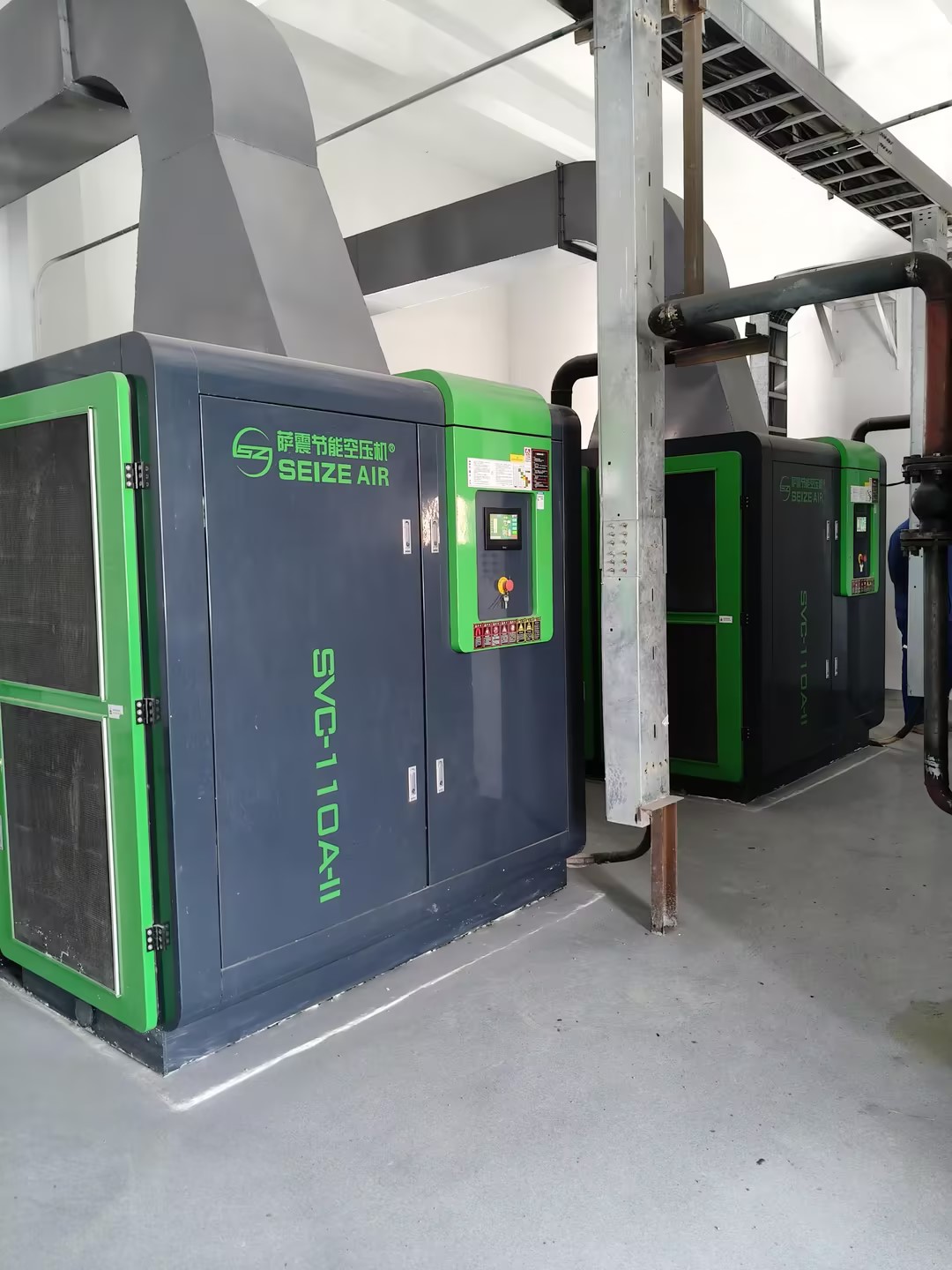
Inside the housing, the rotor doesn't simply spin through the mist. Its surfaces act as a moving target for every suspended droplet. Because the oil particles have more inertia than the surrounding air, they resist following the sharp directional changes forced by the rotating blades. Instead, they drift outward under centrifugal force, strike the rotor or the chamber wall, and stick there as a thin, creeping film.
What happens next depends on how fast the rotor turns and how the surfaces are shaped. At higher speeds, the film itself gets sheared and flung into larger droplets, which then hit other wet surfaces and merge. The rotor essentially turns a fine, stable mist into a coarser spray that gravity and baffles can handle. Some designs rely on this repeated impact and coalescence to grow droplets heavy enough to fall out of the air stream.
The net result is that the air leaving the rotor carries far less oil than the air entering it. Rather than filtering the mist through a porous medium, the rotor uses motion and mass difference to separate the two phases. That is why rotor-based breathers and separators often run for long periods without the pressure drop or clogging you would expect from a conventional filter element.
Why Tighter Gaps Aren't Always Better for Sealing
A tighter clearance often looks like an obvious win for sealing because there's less room for fluid to slip through. In practice, though, an extremely small gap can starve the sealing interface of lubricant. Many seals rely on a thin hydrodynamic film to cool the lip and reduce friction. If the gap is too tight, that film breaks down, the contact zone overheats, and the elastomer or PTFE lip hardens, cracks, or wears prematurely. The result is a seal that fails earlier than a slightly looser one would.
Mechanical tolerances also play a decisive role. Shaft runout, housing misalignment, and thermal expansion can close a tight gap unevenly. When the gap vanishes on one side, local contact pressure spikes, leading to extrusion, grooving, or uneven lip wear. A slightly larger gap gives the seal room to track the shaft and follow its motion without pinching or tearing.
In dynamic applications, especially at high surface speeds or under pressure, an ultra-tight gap can increase frictional heat to the point where the sealed fluid degrades or the seal material loses resilience. Allowing a modest gap often keeps the sealing lip cooler, preserves the lubricant film, and extends service life. So the best seal is not necessarily the one with the smallest clearance, but the one that balances leakage control with the need for lubrication, heat dissipation, and tolerance absorption.
Keeping Discharge Air Below Limits in Flooded Screws
Flooded screw compressors run a constant battle against discharge air temperature. The oil that seals and cools the rotors also picks up heat, and if that heat isn't pulled out fast enough, the air leaving the machine climbs past safe thresholds. Operators often mistake a high reading for a simple thermostat issue, but the root cause usually hides in the thermal mass of the oil system itself. A clogged oil cooler, low oil level, or even the wrong viscosity can push discharge temps up in minutes, and once the oil starts to degrade, the problem feeds on itself. Watching the temperature differential across the cooler gives a far better early warning than waiting for the high-temp alarm.
Most flooded screw packages rely on a thermostatic bypass valve to keep oil warm enough to avoid condensation, yet that same valve can cause trouble when it sticks partially open. Warm oil recirculates instead of heading to the cooler, and the compressor's discharge air creeps upward even on mild days. Add in a dirty aftercooler or a fouled water side on a water-cooled unit, and you get a compounding effect that no amount of thermostat tinkering will solve. Field experience shows that a ten-degree rise in ambient temperature rarely explains a thirty-degree jump in discharge air, so the smart move is to check the oil bypass and cooler approach temperature before touching any setpoints.
Preventing discharge air from crossing the upper limit means thinking about heat rejection as a moving target. Load profile changes, humidity swings, and even minor oil carryover into the air side can shift the balance. Instead of relying on a single sensor reading, trend the discharge temperature against package inlet temperature and oil injection pressure. A slow upward drift over weeks points to oil degradation or cooler fouling, while a sudden spike after a service interval often means an air pocket in the cooling circuit or the wrong oil-to-air ratio. Correcting these issues early keeps the discharge air in a safe band and extends the life of separator elements and downstream dryers.
Oil Separation Returns the Lubricant to Circulation
In closed-loop lubrication systems, oil separation is the step that keeps the fluid viable. Without it, entrained air, moisture, and fine debris accumulate, turning the lubricant into a wear accelerator instead of a protective film. The separator intercepts the return flow before it reaches the reservoir, stripping out these contaminants so the same oil can safely circulate again.
Most separators rely on density differences—centrifugal force or coalescing media push water and solids out of the oil stream, while vacuum chambers pull dissolved gases free. The cleaned lubricant then flows back into the main loop at near-original viscosity and additive balance. Even small amounts of residual water or air can cause cavitation or oxidation, so the separation stage must run continuously, not just during scheduled maintenance.
A well-tuned separation unit extends drain intervals and reduces the risk of tribological failures. Pumps and bearings see a steadier film thickness, and heat exchangers stay free of sludge buildup. Rather than treating oil as a consumable, the system returns it to circulation in a condition close to fresh fill—cutting both operating cost and unplanned downtime.
Why Oil Carryover Is Rarely Zero and What That Means for Your Air System
Oil carryover in compressed air systems is often perceived as a minor nuisance, but the reality is far more nuanced. Because rotary screw compressors rely on oil for sealing, cooling, and lubrication, a certain amount of oil inevitably makes its way past the separation elements. Even with advanced coalescing filters and high-efficiency air/oil separators, achieving true zero carryover is practically unattainable in continuous operation. Temperature fluctuations, fluctuating loads, and aging seals all contribute to small but persistent oil migration downstream.
What does this mean for your air system? The residual oil, even at trace levels, can accumulate inside piping, valves, and pneumatic tools over time. This film attracts dust and debris, leading to blockages or reduced component lifespan. In food and beverage, pharmaceutical, or electronics manufacturing, even a few parts per million of oil can contaminate products or damage sensitive processes. Understanding that zero is not a realistic target helps you shift focus to controlling and monitoring acceptable limits rather than chasing an impossible absolute.
Practical steps include regular inspection of separator differential pressure, investing in high-quality downstream filtration like activated carbon towers for critical applications, and implementing routine oil content testing. By accepting that some carryover will always exist, you can design redundancy and maintenance schedules that keep your air system reliable and compliant without over-engineering for a phantom zero.
FAQ
Air gets pulled into the compression chamber where oil is continuously sprayed. This oil seals the tiny gaps between the rotors, removes the heat generated by compression, and lubricates the moving parts. The air and oil leave the chamber as a mist, and then a separator spins out most of the oil before the air moves on.
The oil does more than reduce friction. Because rotary screw compressors have clearance between the rotors, oil fills those gaps and prevents air from slipping back to the intake side. That dramatically improves volumetric efficiency. It also absorbs a large portion of the compression heat, keeping discharge temperatures manageable.
The discharge stream passes through a separator tank where centrifugal force and gravity pull out the heavier oil droplets. From there, a coalescing filter catches the fine mist that remains. By the time air leaves the receiver, only a tiny fraction of oil carries over, usually just a few parts per million.
Oil sits in a sump or separator tank, then an oil pump or pressure differential pushes it through a filter and into the compression chamber. After mixing with air and being compressed, the oil returns to the separator, gets cooled in an oil cooler, and flows back to the injection point. It’s a continuous loop.
Yes, very much. If the oil runs too cool, water vapor in the air can condense and mix with the oil, forming sludge. If it runs too hot, the oil can break down and lose its sealing and lubricating ability. Most systems aim for a stable operating temperature, often controlled by a thermostatic valve on the oil cooler.
An oil-injected unit relies on oil inside the compression chamber for sealing, cooling, and lubrication. An oil-free machine has no oil in the compression space; it depends on precision machining, special coatings, and external cooling. That makes oil-free air simpler to keep clean but usually more expensive to build and run.
The main ones are oil level, oil quality, and separator condition. Running low on oil starves the injection point and causes overheating. Old or contaminated oil loses viscosity and can block the oil filter. A saturated separator element raises pressure drop and lets more oil carry over into the air line.
A small amount of carryover is unavoidable in oil-injected machines, but it is kept very low through proper separation and filtration. Regular servicing of the separator cartridge, maintaining the correct oil level, and avoiding excessive discharge temperatures all help keep the air clean enough for most industrial uses.
Conclusion
In an oil-injected screw compressor, lubrication and sealing start long before the air reaches the discharge port. A controlled stream of oil is introduced into the intake or directly into the compression chamber, where it collides with incoming air and forms a fine mist rather than a simple liquid film. This mixture is essential because the oil not only cools the rotors and housing but also fills the microscopic clearances between the male and female rotors. As the rotors spin, they trap pockets of this oily air and progressively reduce their volume, which compresses the gas while the oil continuously absorbs heat. Interestingly, the design does not aim for zero clearance. Extremely tight gaps can cause metal-to-metal contact under thermal expansion or slight misalignment, leading to rapid wear. Instead, the oil film itself provides a dynamic seal, and a small but deliberate clearance allows the rotors to turn freely while maintaining compression efficiency.
Once the compressed air leaves the rotor chamber, its temperature and oil content must be managed carefully. The oil acts as a coolant, so discharge temperatures in flooded screws typically stay well below those of oil-free machines, often under 100°C if the thermostatic valve and cooler are working correctly. The next step is recovering the oil. The air-oil mixture enters a separator vessel where most of the oil drops out by gravity and centrifugal action, returning to the oil sump for reuse. Coalescing filters then capture finer droplets, but no separation process is perfect. A tiny amount of oil vapor and aerosol always remains in the outlet air. This residual carryover, usually a few parts per million, may seem negligible, but it can affect sensitive downstream processes, pneumatic tools, or painting applications. For this reason, additional filtration or air treatment is often required depending on the air quality class the system must meet.
Contact Us
Contact Person: Mia
Email: [email protected]
Tel/WhatsApp: +86 19821985894
Website: https://www.seize-air.com